Home

Main navigation

  • Home
  • Products
    • Fish Dual Y Cable
    • 2018-2024 Cummins Bypass Cable
    • BenchForce(TM) Accessories
    • CSP5/L5P Switch
    • Fuel Injector Connectors
    • Special Limited Edition 1-5 Stickers
    • Pig Tails
    • Nissan Titan Unlock Cable
    • Fish Tuning Accessories
    • (Custom) AutoCal® Stickers
    • DSP5 Switches and Keylocks
    • DSP5 and CSP5/CSP4 Decals
    • Custom Decal Virtual Generator
    • Ford, Cummins/Titan and LML Switches
    • Advanced Dual & Triple CP3 Controllers
    • Rear Window Decals
    • Digital Switches
    • Universal Analog Switch
    • Scan and Tune
    • DSP2/High Idle Switches
    • Apparel
  • Spare Parts
  • FAQs
    • 2018-2024 Cummins Bypass Cable Installation
    • Adjusting Vane Position
    • Beginning BBX Flashing
    • Building DSP5 segments
    • Building a script
    • CP3 Testing
    • DSP5 Swap Ends
    • Duramax Logging 101
    • Easy Unit Conversions
    • Error Codes
    • Flashing Your New Tune
    • Installing your Dual CP3 Controller
    • LBZ Pump in LB7
    • Learning to Tune
      • Learn
      • Master EFI Tuner - GM EFI
    • Link an Autocal to a V2
    • Mounting Bracket Installation Instructions
    • Reading Your Tune
    • Troubleshooting Switches
    • USB Driver Solutions
    • Where Do I Find That Table?
    • Working with Scripts
    • Troubleshooting a Cummins/Titan EZ LYNK Switch
    • Bought a Truck and It Has A Switch Already
    • Install your DSP5
    • Install a CSP5 Switch in an L5P
  • Testimonials
  • Links
  • Contact Us
User account menu
  • Log in

Breadcrumb

  1. Home

Troubleshooting a Cummins/Titan Switch

Measurements for testing a Cummins/Titan (red/white/black) switch (NOT a CSP5 OBD II switch) with a meter:

The wire should be soldered into the board in the following order
        Black above the "C"
        White above the "um"
        Red above the "mm"

Test Voltage with switch plugged in and key on, test resistances with switch unplugged.

        Red to white resistance = 2200

        Black to red     voltage = 5V

        Black to white:

               Pos 1:  resistance = open    Voltage = 5.0V  
               Pos 2:  resistance = 5600    Voltage = 3.5V  
               Pos 3:  resistance = 2200    Voltage = 2.5V
               Pos 4:  resistance = 1000    Voltage = 1.5V
               Pos 5:  resistance =   270    Voltage = 0.5V

PRO TIP: If when you try to insert the pins they don’t stay in the gray connector… If the red insert inside the gray connector is pushed too far down OR if you plug the connector in and somehow push the red connector down BEFORE you insert the pins, then you need to pull the red insert back out FIRST. To do this, you can either stick a hook or probe into one of the two bigger slots on the red insert and pull it up slightly OR grab the small protruding piece of the red insert with a small pliers and pry it up that way We hope this helps you and your customers!

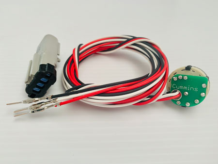
Here is a picture of a Cummins/Titan switch for your reference!

Social Media!

Find us on facebook

Youtube

Instagram
Find us on Instagram

What's New?

Fish Tuning Dual Y/Splitter OBD II Cable
DSP5/CSP5 1-5, 5-1, 1-4 & CUSTOM Decals
Custom Decal Virtual Generator
Nissan Titan Unlock Cable (Auto Agent 2 only)
Fuel Injector Connectors
Apparel

We don't tune anything, but "EFILive®," "AutoCal®" and "FlashScan®" are registered trademarks of EFILive® Limited.

"EZ LYNK®" is a registered trademark of EZ LYNK® SEZC.